
www.industry-asia-pacific.com
22
'22
Written on Modified on
Tackling harmonics in inverter applications
“Non-linear means it's hard to solve” once said Arthur Mattuck, the Massachusetts Institute of Technology (MIT) mathematician. But non-linearity should be solved when it applies to electric loads, as it generates harmonic currents that have negative — and costly — effects on electrical distribution. Here, Marek Lukaszczyk, European and Middle East marketing manager at WEG, the global manufacturer and supplier of motors and drive technology, explains how harmonics can be mitigated in inverter applications.
Reducing harmonics in electric loads can yield energy and cost savings.
Fluorescent lamps, switched-mode power supplies, electric arc furnaces, rectifiers and frequency inverters. All are examples of devices with a nonlinear load, which means the device draws voltage currents in abrupt short pulses. They differ from devices with a linear load — like motors, space heaters, transformers after power-up and incandescent light bulbs. With linear loads, the relationship between the voltage and current waveforms are sinusoidal, and the current at any time is proportional to the voltage — stated by Ohm’s law.
A problem with all nonlinear loads is they produce harmonic currents. Harmonics are frequency components that are generally higher than the mains fundamental frequency, between 50 or 60 hertz (Hz), and add to the fundamental current. These additional currents cause the system voltage waveform to distort and reduce its power factor.
Harmonic currents flowing in an electrical system can produce other unwanted effects, such as voltage distortions at interconnection points with other loads, cable overheating and so on. In these instances, the Total Harmonic Distortion (THD) measurement can tell us how much of the distortion of a voltage or current is due to harmonics.
In this article, we’ll look at how you can mitigate harmonics in inverter applications, according to recommendations used by industry for the proper monitoring and interpretation of phenomena that cause energy quality problems.
The UK uses the Energy Networks Association (ENA)’s Engineering Recommendation (EREC) G5 for good practices in managing harmonic voltage distortion on transmission systems and distribution networks. In the European Union, these recommendations are normally covered by the electromagnetic compatibility (EMC) directive, which includes various International Electrotechnical Commission (IEC) standards such as IEC 60050. IEEE 519 is generally the North American standard, though it’s worth noting that IEEE 519 concerns distribution systems and not individual devices.
Minimising harmonics
Once the level of harmonics has been identified through simulation or measurement, there are numerous ways to minimise them to keep them within acceptable limits. But what are the acceptable limits?
Because it’s not economically feasible, or possible, to eliminate all harmonics, there are two EMC international standards to limit mains voltage distortion by prescribing the maximum value for harmonic currents. They are the IEC 61000-3-2 standard, which applies to equipment with a rated current up to 16 amps (A) and ≤ 75 A per phase, and the IEC 61000-3-12 standard for equipment above 16 A.
The limits on voltage harmonics should be to keep the THD (V) at ≤5 per cent at the point of common coupling (PCC). The PCC is the point where the electrical conductors of the distribution system are connected to the customer's conductors and where any transfer of electric power between the customer and the distribution system takes place.
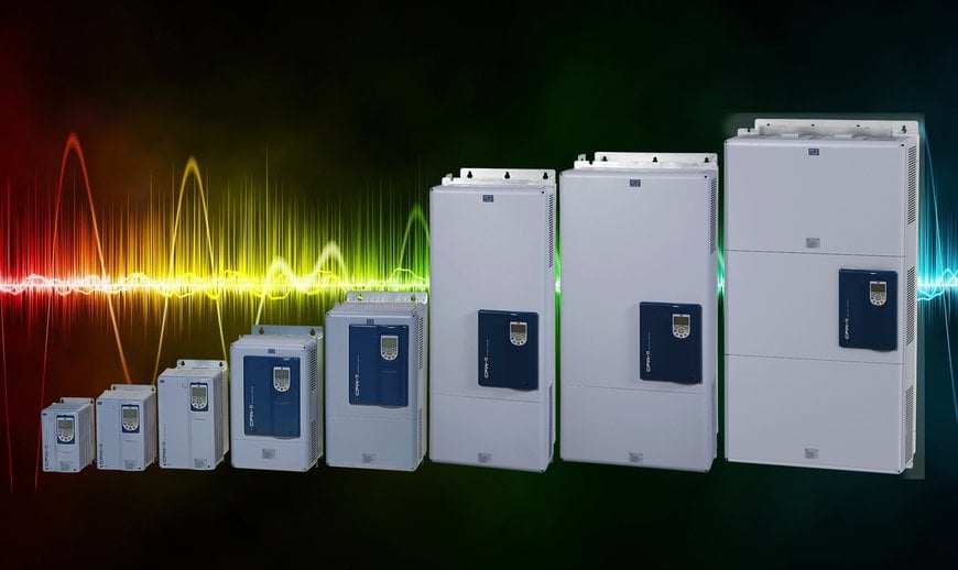
This recommendation of ≤5 per cent has been adopted as the sole requirement in many applications. That is why, in many cases, just using inverters with a 6-pulse rectifier and an input reactance or direct current (DC) link inductor is enough to meet maximum voltage distortion recommendations. Certainly, the use of inverters with DC link inductor — examples include WEG’s own CFW700 and CFW500 — significantly reduces harmonic emission compared to 6-pulse inverters without an inductor in the link.
Otherwise, there are several other options for mitigating harmonics in the system in inverter applications, which we’ll look at here.
Possible solutions
One solution to mitigate harmonics is with the use of inverters with 12-pulse rectifier. However, this method is usually only used if the transformer is already installed; for multiple inverters connected to the same DC link; or if a new installation requires a transformer dedicated to the inverter. In addition, this solution is applied to powers generally greater than 500 Kilowatts (kW).
Another method is to use a 6-pulse active current (AC) drive inverter with a passive filter at the input. This method can coordinate harmonic voltages between different voltage levels — medium (MV), high (HV) and extra-high voltage (EHV) — and support compatibility and eliminate adverse effects on customers’ sensitive equipment. While this is a traditional solution to mitigate harmonics, it increases heat losses and reduces the power factor.
This brings us to more costly methods of reducing harmonics: the use of inverters with an 18-pulse rectifier or, specifically, a DC-AC drive fed by DC link through 18-pulse rectifier and phase-shifting transformer. The pulse rectifier is the same solution whether it’s 12 pulse or 18 pulse. While this is a traditional solution to mitigate harmonics, due to the high cost, this solution is usually only used if the transformer is already installed or if a new installation requires a transformer dedicated to the inverter, with powers generally greater than 500 kW.
Whereas some methods of harmonic mitigation can increase heat losses and reduces the power factor, others can improve system performance. A great solution, that we recommend, is the use of a WEG active filter with a 6-pulse AC drive. This is a great solution to eliminate harmonics generated by various devices
Finally, another solution is attractive when it’s possible to regenerate power to the grid, or when several motors are driven by a single DC link. That is, to use an active front end (AFE) regenerative drive plus an LCL filter. In this instance, the drive has an active rectifier at the input and complies with recommended limits.
Network reactance
For inverters with no DC link — like WEG’s own CFW500, CFW300, CFW100 and MW500 inverters — the key to mitigating harmonics is network reactance. This not only tackles issues with harmonics, but also with energy becoming stored in the reactive parts of the inverter which becomes unproductive. With network reactance, controlled reactance can be achieved with a high frequency single phase inverter loaded by a resonant network. The advantages of this approach are lower energy stored in reactive elements and lower harmonic distortion.
There are other pragmatic methods for tackling harmonics. One is to increase the number of linear loads in relation to nonlinear loads. Another is to separate the supply systems for linear and nonlinear loads, to thus have different voltage THD limits between five per cent and ten per cent. This approach complies with the aforementioned Engineering Recommendation (EREC) G5, plus the EREC G97 for assessing harmonic voltage distortion from non-linear and resonant plant and equipment.
A further method is to use a rectifier with a greater number of pulses, feeding it through a transformer with multiple secondaries. Multiple winding transformers, with more than one primary or secondary winding, can be connected to each other in some special type of configuration to provide the required output voltage levels or drive a number of loads at the output, for more options and flexibility within the distribution system.
Lastly, there is regenerative drive operation with the AFE, mentioned above. Basic AC drives are not regenerative, meaning they cannot return energy to the power source — which is insufficient especially as, in some applications, it is a specific requirement to recover the returned energy. If the regenerated energy needs to be returned to the AC supply, then this is the role of a regenerative drive. The simple rectifier is replaced by an AFE inverter, and it’s through this method that the energy can be recovered.
These methods provide several options to combat harmonics, suited to different kinds of distribution systems. But they also yield significant energy and cost savings in a variety of applications, and in accordance with international standards. These examples show that non-linearity needn’t be hard to solve, with the right inverter technologies in place.
www.weg.com
