
www.industry-asia-pacific.com
08
'20
Written on Modified on
Muting reinvented - Smart Process Gating
The "Smart Process Gating" muting process, which completely forgoes the need for signal-emitting sensors, is based on the MLC safety light curtains from Leuze electronic and is integrated in the MLC 530 SPG model.
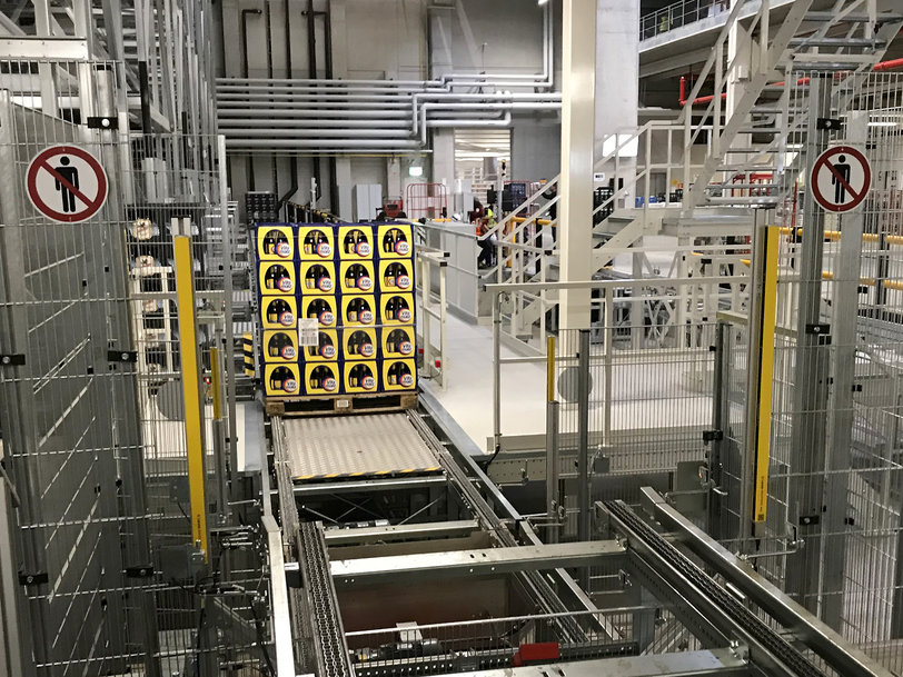
Handling and mounting systems often contain danger zones which must be protected against unauthorized access. However, material transport must be able to enter and exit the danger zone at the same time. Examples of systems such as this can be found in intralogistics, the automobile industry and the packaging industry. In practice, these requirements are met using optoelectronic protective devices which are installed at the channeling and diverter stations. These protective devices must be designed so that they detect the approach of the transport material at the protective field, and then temporarily bridge the protective field. Fault-free passage of the transport material is therefore guaranteed. The protective field may only be bridged when transport material is approaching - access by persons must be prevented.
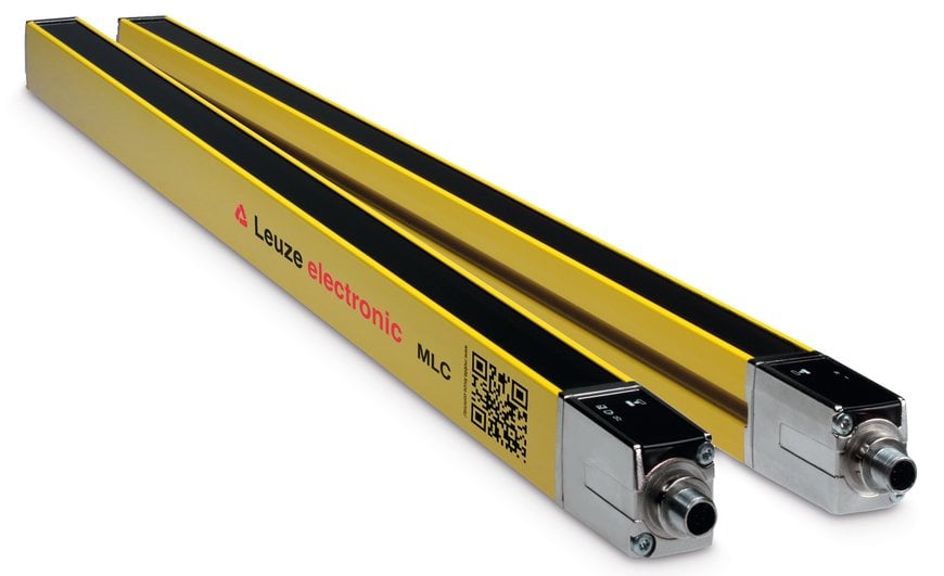

Figure 1: MLC SPG 530 safety light curtains
Until now, additional sensors were required for detecting the transport material – and therefore also for distinguishing between transport material and persons. These are also referred to as ‘muting sensors’. The "Smart Process Gating" (SPG) principle meets the above-mentioned requirements without the need for additional sensors.
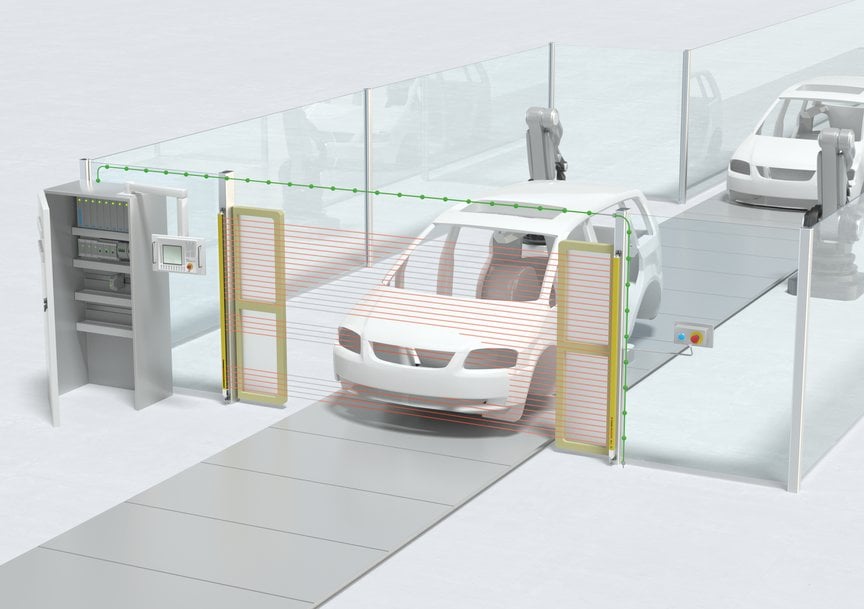
Figure 2: Process-controlled access guarding with Smart Process Gating (SPG).
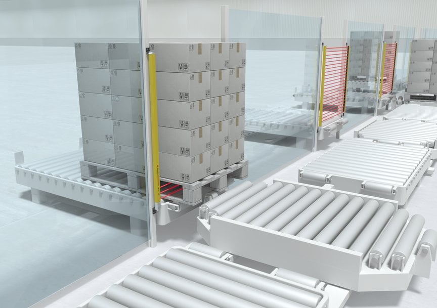
Figure 3: SPG allows for a very compact system arrangement with material locks.
The operating principle
The Smart Process Gating principle (SPG) is based on type 4 safety light curtains of the MLC 500 series from Leuze electronic. It is implemented in the MLC 530 SPG model. In the basic principle, the SPG principle uses two control signals (figure 3): The first signal (CS = Control Signal) is provided by the system control (PLC). The point in time for the generation of the CS switching signal must be set such that the transport material is within 200 mm of the protective field. This is necessary to prevent persons from slipping through. The second signal (PFI = Protective Field Interruption) is generated by the safety light curtain itself upon interruption of the protective field by the transport material. Bridging (gating) of the protective field is thereby started as well. Gating ends either after a fixed time (t), after the transport material has exited the protective field again or by actively resetting the switching signal CS.
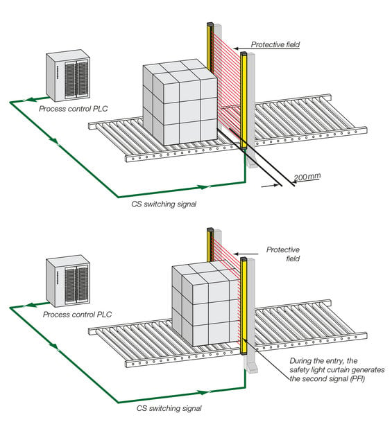
Figure 4: Overview of the operating principle.
Signal response in detail
Once the system control (PLC) has sent the switching signal (CS) to the safety light curtain, the transport material must enter the protective field within 4 seconds (t1, figure 4). During entry, the safety light curtain generates the second signal (PFI) and, thus, starts the bridging of the protective field (gating). With the basic setting, the transport material must pass through within 10 minutes, otherwise the receiver of the safety light curtain goes into interlock state. Alternatively, a timeout extension of up to 100 hours can be activated, in order to permit stops during a shift change or over a weekend, without blocking the gating sequence.
When the transport material exits the protective field, the safety light curtain resets the signal that it generated (PFI) as soon as the transport material leaves the protective field. Depending on the selected operating mode, the protective field is then either automatically switched on again after 1 or 2 seconds (t2) by the safety light curtain or gating is ended by the control. Access guarding is now active again.
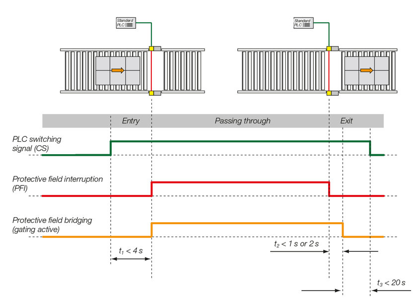
Figure 5: Typical signal progress whilst transport material is passing through the protective field.
Application-optimized operating modes
The SPG principle works in three operating modes in order to adapt to different areas of application. These are implemented in the MLC 530 SPG safety light curtain (table 1).
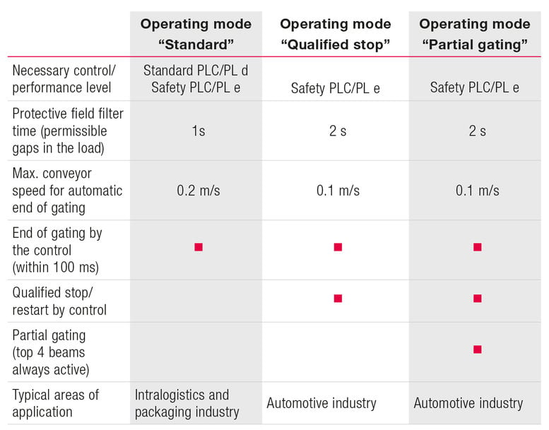
Table 1: Overview of the operating modes.
The "standard" operating mode is used above all in applications in the intralogistics. The integrated filter time of 1 second means that the light beams of the light curtain are allowed to have an unobstructed view for a time window of up to 1 second,
i.e., they may not be interrupted by the transport material. This means that gaps are permitted in the transport material, such as those that occur when a pallet is being loaded, without the Gating process being terminated. Once the transport material has left the protective field, the protective function is re-activated after 1 second when using the automatic end of gating. It must also be ensured that the gap between the transport material and protective field is no more than 200 millimeters when the transport material is exiting from the protective field in order to prevent persons from entering. If the transport material moves more than 200 millimeters from the protective field within the re-activation time of 1 second, the gating can be terminated prematurely using the "End by control" function. This is done by resetting the CS signal. Gating is terminated within 0.1 seconds and then the protective function is re-activated (figure 4). Depending on the required performance level, the "standard" operating mode can be operated with a standard PLC or with a safety PLC. The timeout extension to 100 hours is supported.
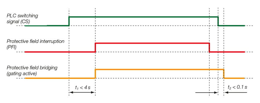
Figure 6: Signal response with "End by control" function.
The "qualified stop" and "partial gating" operating modes are optimized for low conveyor speeds as are common in, e.g., the automotive sector. At slow speeds, the conveyor process can stop extremely quickly. Since the SPG process requires the protective field to be interrupted no more than 4 seconds after activation by the switching signal (CS), these operating modes have the additional function "Qualified stop/restart". This allows an initiated SPG sequence to be interrupted within the 4 seconds (qualified stop) and then restarted. The process can therefore continue operating without interference, even in the event of an unplanned stop. In these operating modes, two switching signals with antivalent signal edges are used by the PLC. The PLC switching signal (CS) and the timer hold signal (TH) (figure 7), which initiate the gating sequence and also control the qualified stop and restart. The TH signal must change with the CS within 0.5 seconds. This operating modes require a safety PLC. The timeout extension to 100 hours is supported.
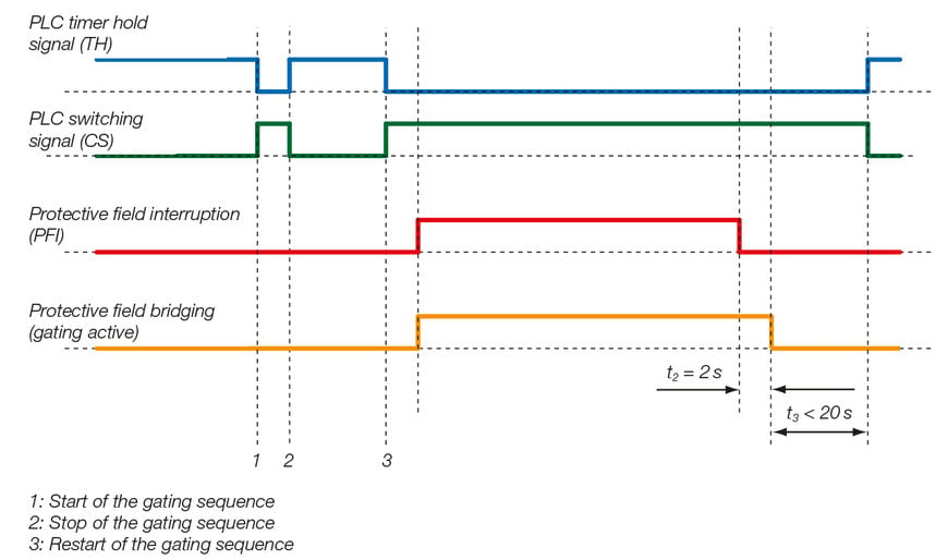
Figure 7: Signal progress whilst transport material is passing through the protective field
With respect to sequence, the "partial gating" operating mode corresponds to the "qualified stop" operating mode. However, with partial gating, the top four beams are excluded from gating. Interruption of these beams always results in shutdown of the OSSDs. Thus, the light curtain can, for example, also simultaneously monitor the closing state of pendulum flaps (figure 8) or detect an unauthorized riding along on transport material.
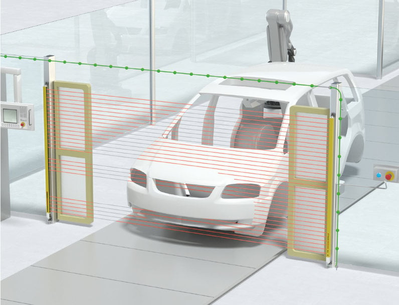
Figure 8: Example for the use of the "qualified stop" and "partial gating" operating modes in the automotive industry.
Requirements for a safe solution
The integration of an SPG application into a system is considered to be a system solution as far as safety technology is concerned. This results from the interaction of the safety light curtain, the system control and, if necessary, mechanical elements. In order to do this, the system manufacturer requires experience in safety design, since the manufacturer programs the gating sequence into the PLC and creates the safety system solution. The manufacturer therefore takes responsibility for implementing the overall system. It is therefore important to take the necessary safety-related requirements into consideration with an SPG installation. These are described in the corresponding operating instructions. An important requirement is for the system control (PLC) to be aware of the current position of the transport material. The PLC requires information on when the protective field has been reached and exited by the transport material in order to transmit the necessary switching signals to the safety light curtain at the correct time. This is necessary because the protective field has to be interrupted within 4 seconds of the arrival of the PLC switching signal. In addition, it is necessary to maintain the maximum distance between the transport material and light curtain of 200 millimeters at the start of the gating sequence (entry) and at the end of gating (exit). For the generation of the switching signals by the control, note that these cannot be directly triggered by persons, i.e., cannot be easily manipulated. There are no special requirements on the type of information acquisition. The information can, for example, be acquired from known processes or additional signal sources.
In exit applications in particular, knowledge about the position can often easily be deduced. Examples include exit stations on cross conveyors, the exiting of processing centers as well as exiting when using active conveyors.
Synchronization beams and protective field length
The transmitter and receiver of the safety light curtain must remain in sync in order to receive a valid protective field signal. The uppermost and lowermost light beam of the safety light curtain are used for synchronization, meaning that they act as synchronization beams. These beams may not be simultaneously interrupted during active bridging of the protective field (gating) for more than 60 seconds, so that the gating function remains functional in regards to safety. In typical intralogistics applications, the gating function is only active for a couple of seconds, i.e. the time needed by the transport material to pass through the light curtain. As this duration is significantly lower than the allowed 60 seconds, the synchronization beams do not have any specific requirements for the dimensioning of the protective field length.
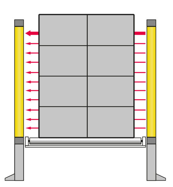
Figure 9: Arrangement of the light curtain for gating times up to 60 seconds
If the transported material requires more than 60 seconds to pass through the light curtain or if the maximum permissible timeout values of 10 minutes or 100 hours are to be exceeded, it must be ensured that at least one synchronization beam remains available at all times. This can be achieved in two ways:
The uppermost beam acts as the synchronization beam. The height of the light curtain is selected so that the synchronization beam is always above the highest point of the transported material (Figure 10 on the right). The lowest beam acts as the synchronization beam. The protective field is arranged so that the synchronization beam is, for example, below the conveyor line. By doing this, the beams of the safety light curtain are partially interrupted by the conveyor line. This area can be hidden with the "Fixed beam blanking with 1 beam tolerance" function (Figure 10, on the left).
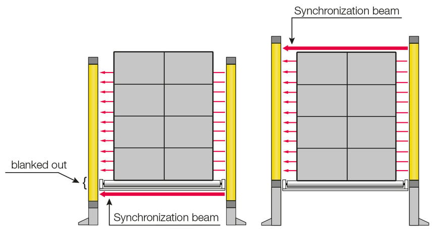
Figure 10: Arrangement of the light curtain if gating times > 60 s are required
Standards and specifications
The MLC 530 SPG safety light curtain specification is designed in accordance with the safety-relevant, international standards.
The data of the sensor is type 4 (IEC/EN 61496), performance level PL e/ category 4 (EN ISO 13849-1) and SIL 3 (IEC 61508). The sensors and the associated documentation concerning the integration of the solution are independently certified. All aspects that need to be noted in order to use the system are described in the operating instructions.

Advantages of the Smart Process Gating
• Extremely compact, space-saving system design, since there is no need to make space for muting sensors in front/behind the light curtain.
• Outstanding reliability and availability of the safety device and low installation and service costs at the same time (no set-up/alignment/realignment of muting sensors).
• Reduced risk of tampering by operating personnel.
• Even parts with openings and pallets with distances between loads are reliably transported.
Author

Jörg Packeiser
Product Marketing Safety
Leuze electronic GmbH + Co. KG
In der Braike 1
73277 Owen
Ph.: +49 7021 573-174
Fax: +49 7021 573-199
E-mail: This email address is being protected from spambots. You need JavaScript enabled to view it.
Web: www.leuze.com
